Bending machine back gauge: there are three points to understand
The backgauge of a press brake is a key component used to position the sheet metal and ensure dimensional accuracy. It plays a vital role in the sheet metal bending process. The following details its function, structural composition, types, operating principle, adjustment methods, and maintenance.
1. What is a press brake back gauge?
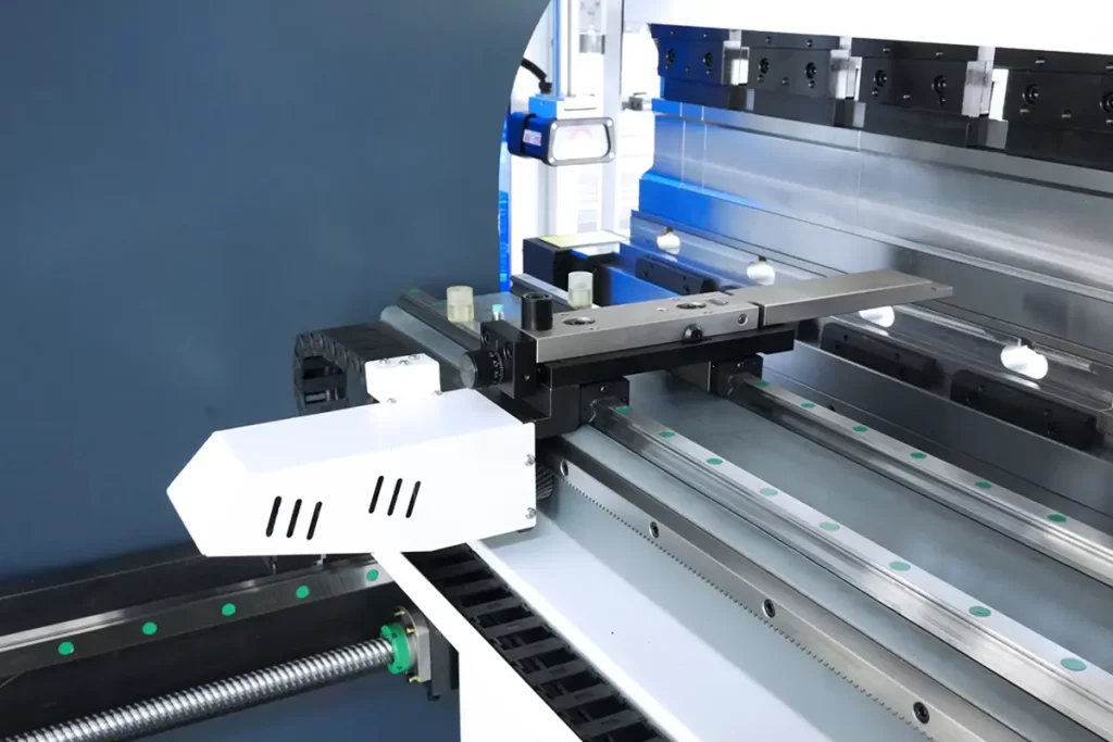
The back gauge of a press brake is a core component for ensuring sheet metal bending accuracy. It is a positioning device installed at the rear of the press brake’s worktable, primarily used to precisely control the workpiece’s position during the bending process, ensuring accurate bending angles and dimensions. Its performance directly impacts workpiece processing quality. The back gauge generally consists of a stop bracket, a stop bracket, a slide, a ball screw, a linear guide, a timing belt, and a servo motor.
The core function of a press brake back gauge is to achieve precise workpiece positioning through the coordinated operation of “mechanical structure + drive transmission + CNC inspection.” The precision and stability of its components directly impact the quality and efficiency of the bending process. While the structural design of the back gauge may vary between different press brake models, the basic principles and key components are similar. High-end models place greater emphasis on automation, intelligence, and optimized precision.
Many customers, when purchasing press brakes, are unsure how to choose the correct back gauge type and are unable to distinguish between the common 4+1-axis, 6+1-axis, and 8+1-axis models. So, what are the differences between these models? Don’t worry. Let me teach you how to choose the type of backgauge so you can achieve the production efficiency and product quality you desire.
2. What is the axis of the press brake’s backgauge?
Common backgauges on press brakes are the X-axis (X1, X2), the R-axis (R1, X2), and the Z-axis (Z1, Z2). They move slightly differently. The X-axis typically controls the left and right movement of the backgauge, the R-axis controls up and down movement, and the Z-axis controls the left and right movement of the stop fingers.
These three axes work together during the bending process to control the position and posture of the backgauge, thereby achieving precise bending of the metal sheet. By precisely controlling the movement of these axes, the CNC system can perform a variety of complex bending operations to meet the needs of various metal processing applications.
Now, let’s explain these axes based on their movement direction and function.
Press Brake X-Axis:
Motion Direction: The X-axis is primarily responsible for the backgauge’s forward and backward movement on the worktable surface, determining the front and back position of the metal sheet during the bending process. The X-axis has a fixed range of motion but can be divided into the X1 and X2 axes for more precise positioning.
Function: By moving the X-axis, the position of the metal sheet in the bending die can be adjusted, thereby controlling the angle and shape of the bend.
Press Bender R-Axis:
Motion Direction: The R-axis primarily controls the up and down movement of the BackGauge stopper fingers, i.e., the vertical position of the BackGauge stopper fingers.
Function: The R-axis movement adjusts the height of the BackGauge, allowing it to accommodate metal sheets of varying thicknesses or achieve different height positioning during the bending process. The R-axis movement also works in conjunction with the X- and Z-axes to ensure the precise position and angle of the metal sheet during the bending process.
Press Bender Z-Axis:
Motion Direction: The Z-axis primarily controls the left and right movement of the BackGauge, i.e., its lateral position.
Function: The Z-axis movement enables independent positioning of the BackGauge stopper, thus accommodating metal sheets of varying shapes and sizes. The Z1 and Z2 axes can independently control the stop fingers on either side of the backgauge, enabling more flexible positioning and bending.
3. How to choose the backgauge configuration for a press brake?
1) If the product primarily requires “right-angle/simple-angle bending” (such as shelves and distribution cabinets): Choose a 4+1 axis configuration for high cost-effectiveness.
2) If the product involves “conical or twisted surfaces” (such as irregular pipes and automotive interior parts): Choose a 6+1 axis configuration, balancing precision and cost.
3) For the production of “ultra-precision curved parts” (such as aviation sheet metal and medical devices): An 8+1 axis configuration is essential, and high-precision inspection equipment (such as a laser tracker) is required.
The fundamental difference between 4+1, 6+1, and 8+1 axis configurations lies in the enhanced “multi-dimensional control capability”—the more axes, the more precise the machine’s control of workpiece posture and mold compensation, but this also increases the cost and technical barriers. Companies need to choose the appropriate axis configuration based on product precision requirements, production batch size and budget to avoid problems such as “over-configuration” or “undercapacity”.